


Extra: Latched series-elastic with a twisted string
Finding a physical implementation of the hold-release jump strategy


In the previous extra post, I found that the hold-release strategy works well to accelerate a mass within a fixed distance using a motor and spring.


Steps:
Use some sort of latch to hold the leg in place.
Gradually increase the mechanical advantage to wind up the spring at a constant motor speed.
Suddenly release the leg to convert elastic energy to kinetic energy.
This post describes the effort so far for finding ways to physically implement the variable transmissions before and after the spring.
Latched series elastic
This first prototype is a mechanism to hold an output in place while an input winds up a spring. The input is the lever on the right and the output is the lever on the left. A leaf spring connects the two so that rotating the input pushes or pulls the output to rotate as well. A smaller link with 3 protrusions between the levers’ rotation points determines the state of the latch and acts like the pawl in a ratchet.

When the pawl is in the clockwise position, the output link (like the ratchet wheel in a ratchet) cannot be pushed counterclockwise by the spring. If the input lever is rotated far enough counterclockwise, the pawl is pushed out of the way of the ratchet tooth and the output lever is released. To reset the pawl, the input lever needs to travel all the way clockwise.
This goal here is to create an elastic energy storage that can be easily set and reset with control over only one joint—the input lever. This means that the leg will not need an additional servo to serve as the spring release or reset.
The bow leg hopping robot1 uses another design to accomplish this. A pulley on a spinning disk bends a string that deforms a bow-shaped leg, and at a certain disk angle the string slips off the pulley. If the disk continues to spin, the pulley starts bending the string again.
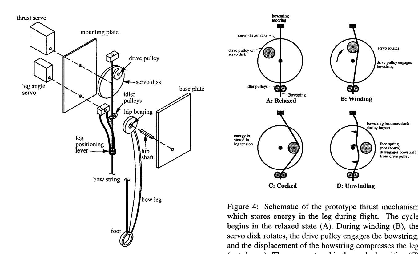
One of the main differences between the designs is that the bow leg detaches the input (the servo motor) from the leg when the elastic energy is released, while our prototype keeps the input link connected to the output through the spring (elastic stays in series). The benefit of a series elastic is that we can still control the released output if the spring is stiff enough, as seen in the first few seconds of our video. This means that are able to quickly retract the leg without needing to wind up the spring again, making it suited for midair adjustments after a jump.
Spring selection
The latched series elastic prototype and bow leg hopper both use bent leaf springs, but what about other shapes? What material would work best?
One project that performed an extensive study of springs for jumping is this rocket-looking robot2:

This is probably the highest-jumping robot in the world, and it uses the hybrid tension-compression spring shown in blue in subfigure a. Using a combination of compressed carbon fiber strips and stretched rubber bands, they could achieve a spring that applies nearly constant force across the entire compression range. The area underneath this force/compression curve represents the energy stored in the spring, so constant force vs. compression means that the energy stored in the spring is maximized for the same motor force limit. For example, if the motor is limited to 10kN of force (or operates the best at 10kN), the best possible spring would take exactly 10kN to compress for the entire distance.
They also considered the material properties of the spring. Below is their Ashby plot of elastic modulus (stiffness) vs. yield strength, both divided by density. We want something with a high yield strength with relatively lower elastic modulus so more work can be done on the material in the elastic region. It should also be lightweight, so these factors make materials to the right of the diagonal line preferable.

Elastomers like latex rubber and fiber reinforced composites like carbon fiber or fiberglass perform the best in these metrics. The authors found that latex rubber could store more energy per kg, but it only works in tension and requires something to constrain it. Therefore, they used the slightly worse carbon fiber to constrain the rubber bands. This combination also helped them achieve a more constant force vs. displacement profile: a linkage with rubber bands only would have a decreasing force, while the compressed carbon fiber strips alone would have an increasing force.

To collect our own spring data, I built this testing stand to bend springs and record their force vs. displacement profile.
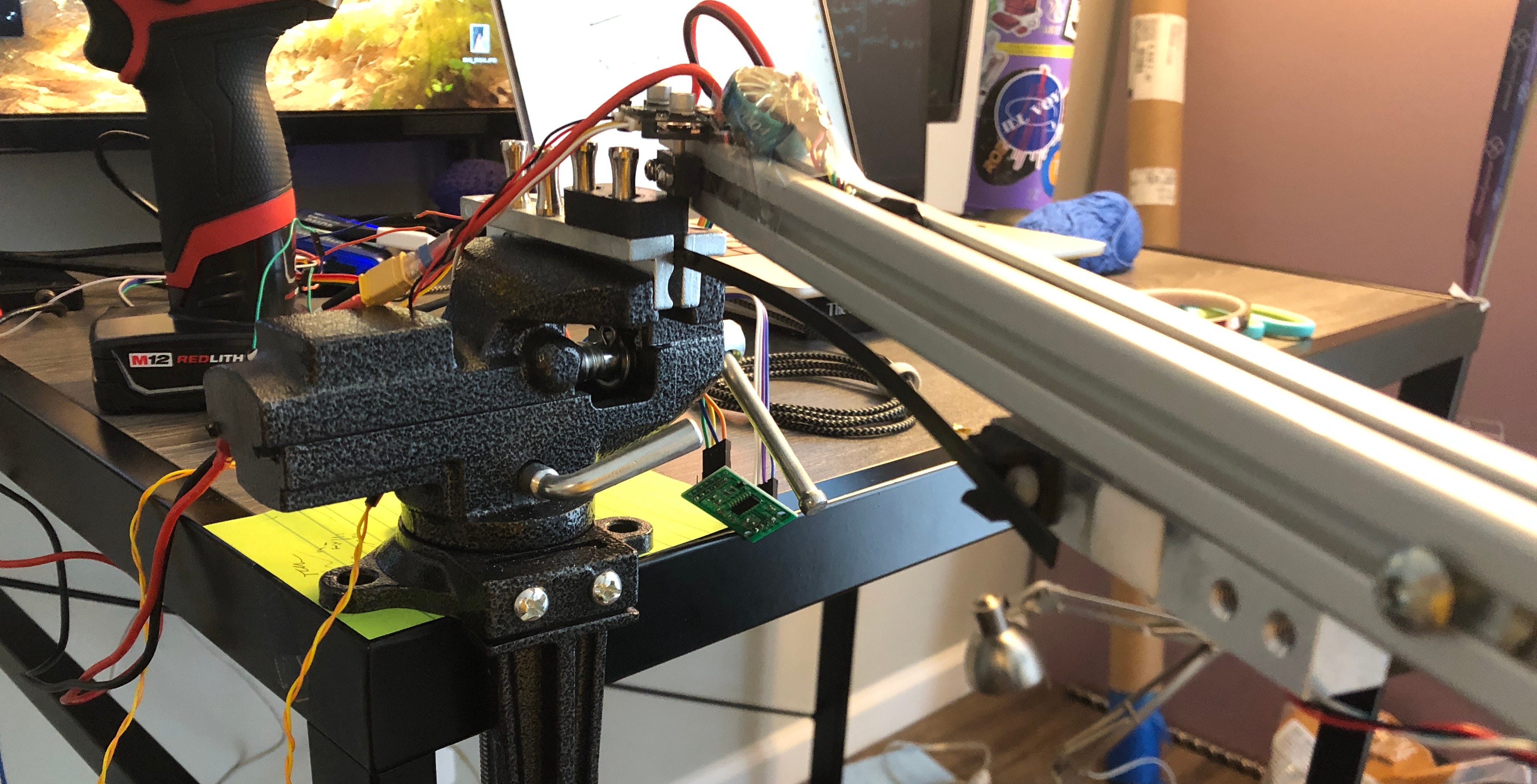
A strip of carbon fiber or other material is clamped in the vise, and the aluminum extrusion rotates around the point where it is clamped. One end of a 5 kg load cell is mounted to the aluminum extrusion, while the other end pushes on the strip to deflect it. A rotary encoder (the motor controller) mounted at the rotation point measures how far strip has deflected. I use an electric drill with a pulley and string to rotate the aluminum extrusion at a consistent rate.
Three trials of two carbon fiber strips of different lengths are plotted below:

We haven’t completely analyzed the data, but the force vs. displacement is very linear as expected for bending a cantilevered beam. We can use the spring constant found here to predict the effective stiffness when the beam is under buckling, for example, when the same strip is forced into other spring shapes.
Using the same test stand, we can also collect data for compression and tension springs by clamping another long aluminum extrusion in the vise, then placing the spring in between the fixed and freely rotating rigid beams at a consistent distance away from the center.
Linkage for constant motor force
If we have a linear spring (like stretching a rubber band), the spring force is naturally going to increase as more energy is stored. To keep the motor force constant, the mechanical advantage between the motor and the spring (ratio of spring force to motor force) would need to increase as a square root function of motor rotation xa as partially derived in the extra post about variable mechanical advantage in series-elastic actuators.

This is the goal for the overall mechanical advantage between the motor and the spring. However, we first want to increase the force of the motor using a twisted string actuator, which has a variable mechanical advantage in itself: as the string gets more twisted it contracts more for the same input rotation, so the mechanical advantage decreases. So, we can try find a linkage in between the twisted string and the spring that results in a good mechanical advantage profile.
An example:
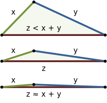
In this linkage, a motor twists a string (blue) that pulls a triangle (purple) which is allowed to rotate at one of its vertices. The other vertex pulls on the end of a spring (red) to store energy. This particular geometry allows for nearly constant motor force (green curve) as the spring stretches.

Algebraic expressions for these quantities plotted are obtained using the law of cosines on the three triangles formed by the motor, string, spring, and fixed points.

The transmission ratio T1 is found using the derivative of the output (length of the spring Lspr) with respect to the input (motor rotation φ). The spring with stiffness k starts off with some force Fspr0, representing any initial stretch. Energy E is calculated with the integral of motor force with motor rotation, and conveniently simplifies due to the derivative present in Fmotor.
I came across the linkage geometry in the figures above just by playing around with the sliders in the Desmos interactive. However, to find the best linkage geometry and string parameters, we can maximize the “straightlineness” of Fmotor, or maximize the energy. Currently, I am working on setting up the optimization problem for energy maximization.
A few challenges to be solved:
What is the maximum rotation of the motor (φmax)? In the desired case when the motor is always putting out the most power, the speed is consistently ωmax / 2, so φmax = ωmaxt / 2 where ωmax is the free speed of the motor and t is the allotted jump time. However with imperfect geometry in the process of optimization this is not going to be the case, so I’ll need to find a end condition for motor rotation. One option is to define φmax as an optimization variable and constrain it to be less than ωmaxt / 2, so the algorithm can choose to end the jump early if needed.
There are a few square roots and inverse cosines in the expression for Lspr. The optimization libraries only support real-valued operations, so square root only works for nonegative numbers and cos-1(x) is only defined for [-1,1]. During optimization, the function is evaluated at unpredictable points and often returns NaN. One option might be to smoothly extend the functions and then apply optimization constraints on the arguments to the functions. I can also look into applying a set of triangle inequality constraints to the side lengths of the triangles, which should make the triangles in the linkage always geometrically possible.

Thank you for reading this extra post! This is mostly practice for technical communication, and in the process of trying to make it understandable I often find new ways of looking at the topic. I hope that these explanations help you understand more details about our squirrel design, and please let me know if you have any suggestions!
 | A guest post by
|
This is so incredibly impressive! I eagerly await the next design updates!