


#12 Winter designs
New springs, new PCBs, new legs

We’re back from winter break! In the past month, we performed more spring tests, evaluated the tradeoffs between latched vs direct drive legs, refined FOC motor control, designed 4 new PCBs, and started revisions for the leg linkages.
Inaccurate spring test data…
(Chris)
Previously, I had collected force-displacement data for buckling carbon fiber strips to see how much energy each of them could store. Unfortunately, I only performed tests on strips cut from the same long strip, and it turns out that the stock was perfectly split down the middle (only seen if forced open). It could have been split from the start, or split as a result of repeated buckling, but this drastically decreased the stiffness and increased the amount it could be compressed before breaking.

I had designed the 2 DOF latched series elastic leg to use 100mm long strips that compress until they are 30mm, which should be safe looking at the initial testing data. When I installed new springs on the actual leg, they snapped immediately. Were these new springs just part of a bad batch? It took a while to realize that the testing data all came from one “bad” strip. I redid the experiments with springs from different batches, and each spring went through increasingly forceful cycles until it ultimately broke. Testing each spring until failure has the benefit of knowing how much force it takes to break, and we can design the mechanism so the spring only experiences up to 80% of its max force, for example. Below is a plot of force vs displacement for 0.6mm springs of different lengths, ranging from 75mm to 200mm long.

Longer springs tend to store more energy before breaking. However, 200mm is too long to fit in squirrel’s hind leg, and shorter springs break too easily. The split spring earlier actually gave some useful insight—a split spring is made of 2 thinner springs, and thinner springs can bend more before breaking. I bought 0.5mm thick strips and tested their characteristics as well:
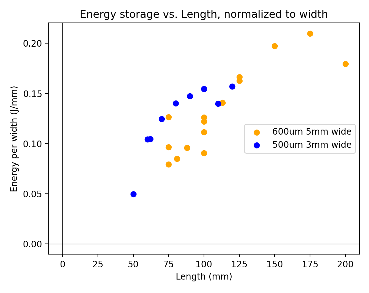
Per milimeter width of the strip, the 0.5mm thick strips performed better than 0.6mm for shorter lengths. We’ll be moving forward with 0.5mm thick 70mm long strips because they are more compact without sacrificing much energy.
I also tried stacking two 0.5mm strips parallel on top of each other, as well as constraining different length strips at an angle in an attempt to get more energy storage in the same width. Stacking them in parallel increased the energy storage, but also significantly increased the hysteresis, so it would take more power to wind up than is released. It was also unreliable because the outer spring would slide out from the joints at either side. The configuration with different length strips at an angle shown below did not work at all. The strips need to rotate different amounts at the joints when buckling, so the constraints resulted in too much bending in shorter strip, snapping it.

Comparing with direct drive
The reason for a latched leg is to allow the motor to generate more mechanical energy than is limited by the leg stroke, by allowing it more time to wind up a spring instead of directly accelerating the mass, as explored in this previous post. But, for the conditions we have, plus losses in the spring, how much more beneficial is latched over a simpler direct drive?
The plots below show analytical solutions to the jump height and vertical jumping agility for both direct and latched legs at various combinations of stroke length, power, time limit, and spring efficiency. Vertical jumping agility (m/s) is a metric defined by Salto’s authors calculated by height per jump multiplied by jump frequency.
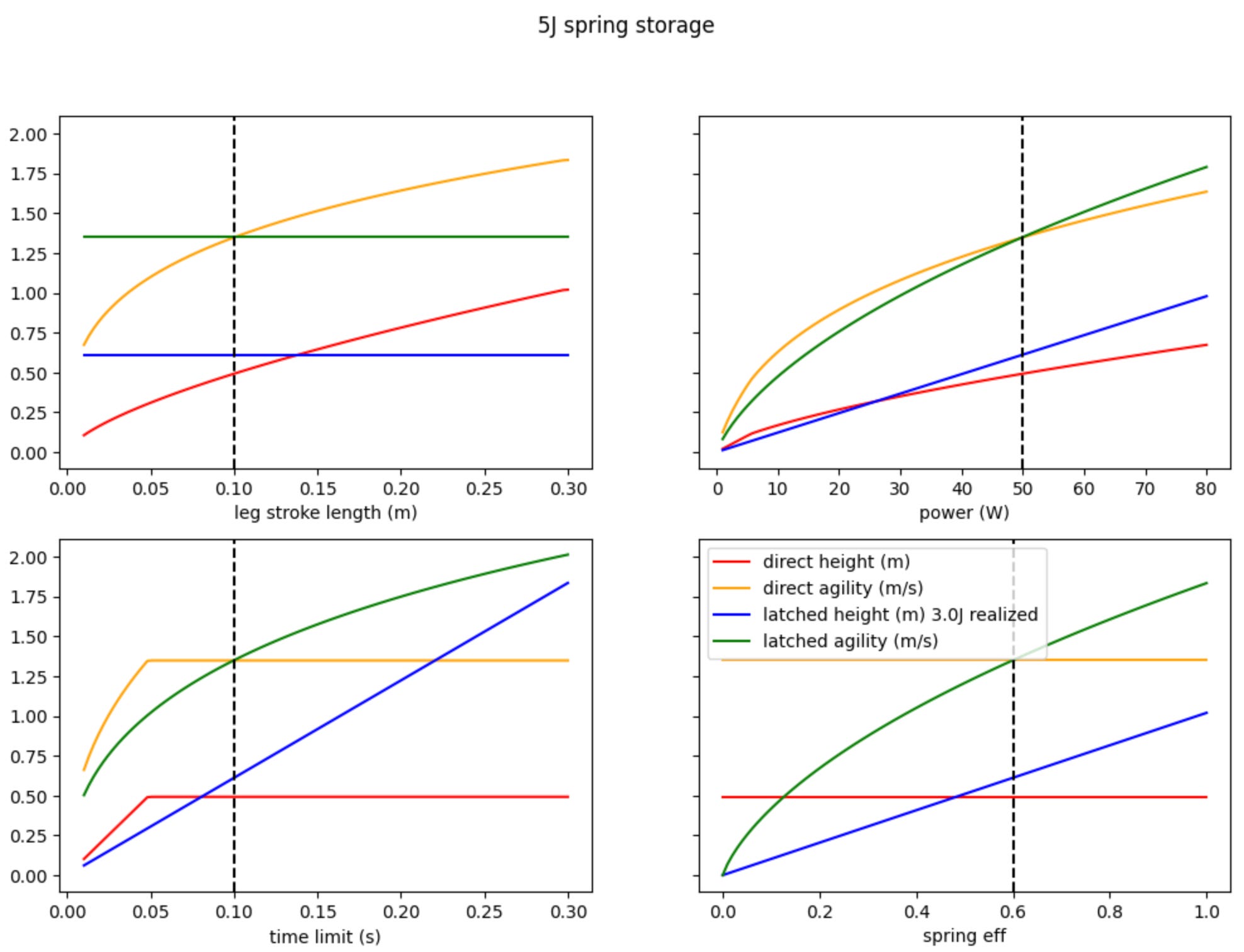
The height that a direct drive leg could reach assuming a perfect transmission is plotted in red, and the corresponding agility in orange. The height and agility for latched leg is plotted in blue and green. In each plot, 3 of the 4 variables are kept constant so we can see the effect of a single variable. Here are some takeaways:
Upper left plot: Direct drive height and agility improve with more leg stroke length, but it doesn’t affect latched.
Upper right: Latched height and agility improve faster than direct drive with respect to motor power.
Lower left: For short time limits, direct drive is better presumably because it does not hit the leg stroke limit. Regardless of how much time after, direct drive has already taken off and cannot make use of the extra time. Latched agility keeps on increasing when time limit is increased—even though each jump takes longer, the jump height increases faster.
Lower right: Latched height increases linearly with spring efficiency.
With a mass of 500g, leg stroke of 100mm, motor power of 50W, jump time of 100ms, and spring efficiency of 60%, the latched leg can beat a perfect direct drive leg in jump height and match its agility. Latched leg is more favored if leg stroke is decreased, motor power increased, jump time increased, or spring efficiency increased. Not plotted, but increasing mass favors direct drive.
We need 5-6J of spring energy to beat direct drive. With 70mm long springs, this corresponds to a width of around 40-48mm. This would be two groups of 7-8 individual strips, each 3mm wide.
FOC motor control
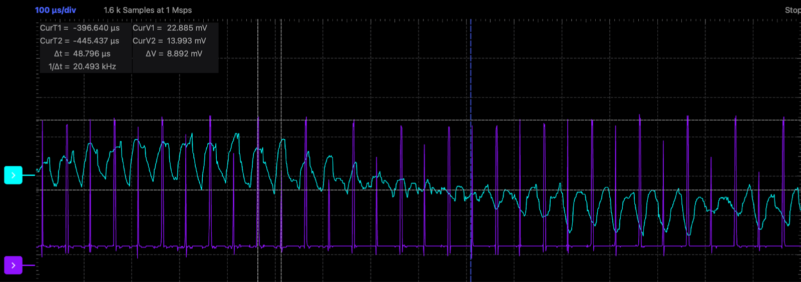
During the demo in December, FOC was inconsistent and only worked for lower power, so we did not run it on the robot. It’s now fixed by properly aligning the ADC readings with the peak current through the shunt resistor, which happens in the middle of the PWM wave when the low-side mosfet is on. There was also an integer overflow in the current control loop gains, which caused it to fail for higher power.
New PCBs
Ø32controller v3 (PCBWay, Github)

New motor controller revision! Changelog:
Changed to 37x 22uF ceramic capacitors instead of 2x 100uF electrolytic capacitors for a thinner PCBA.
Removed I2C to free up GPIOs.
Added an external NTC thermistor port. In previous testing, the motor coils heated up dangerously quickly, so we plan to monitor the stator temperature.
Added an external SPI port to allow for an external encoder by soldering a 6pin 0.5mm pitch FFC.
Some components can be sourced more cheaply, bringing down the components cost to $23 per board.
Test point on LED GPIO for debugging higher speed digital signals with an oscilloscope.
Thank you to PCBWay for sponsoring this board! I used their turnkey PCB assembly service, where PCBWay will source the components and solder them all in one order. This saves a ton of time on our end applying solder paste, placing all the tiny components, and reflowing (twice, for each side). A majority of the cost for the the PCB, components, and assembly was paid for by PCBWay.

Ø12encoder (Github)

This is an external encoder board that mounts onto a 12mm bolt circle, fitting onto the back of the green motor we have. This means we can move the motor driver elsewhere for space-constrained designs, and the encoder communicates with the Ø32 motor driver with SPI. Alternatively, the encoder can be used independently by connecting it to a RS485 bus.
Squirrel Brain (Github)

This PCB replaces the jumble of wires earlier, which consisted of a 5V buck converter, ESP8266, and RS485 transceiver. This time, we have a Seeeduino XIAO ESP32S3 Sense because of its small package and camera, and there’s also a half-duplex UART transceiver for communication with Dynamixel XL servo motors, which will allow much better control of the squirrel’s front legs compared to the hobby servos we were using earlier.
Structural PCB
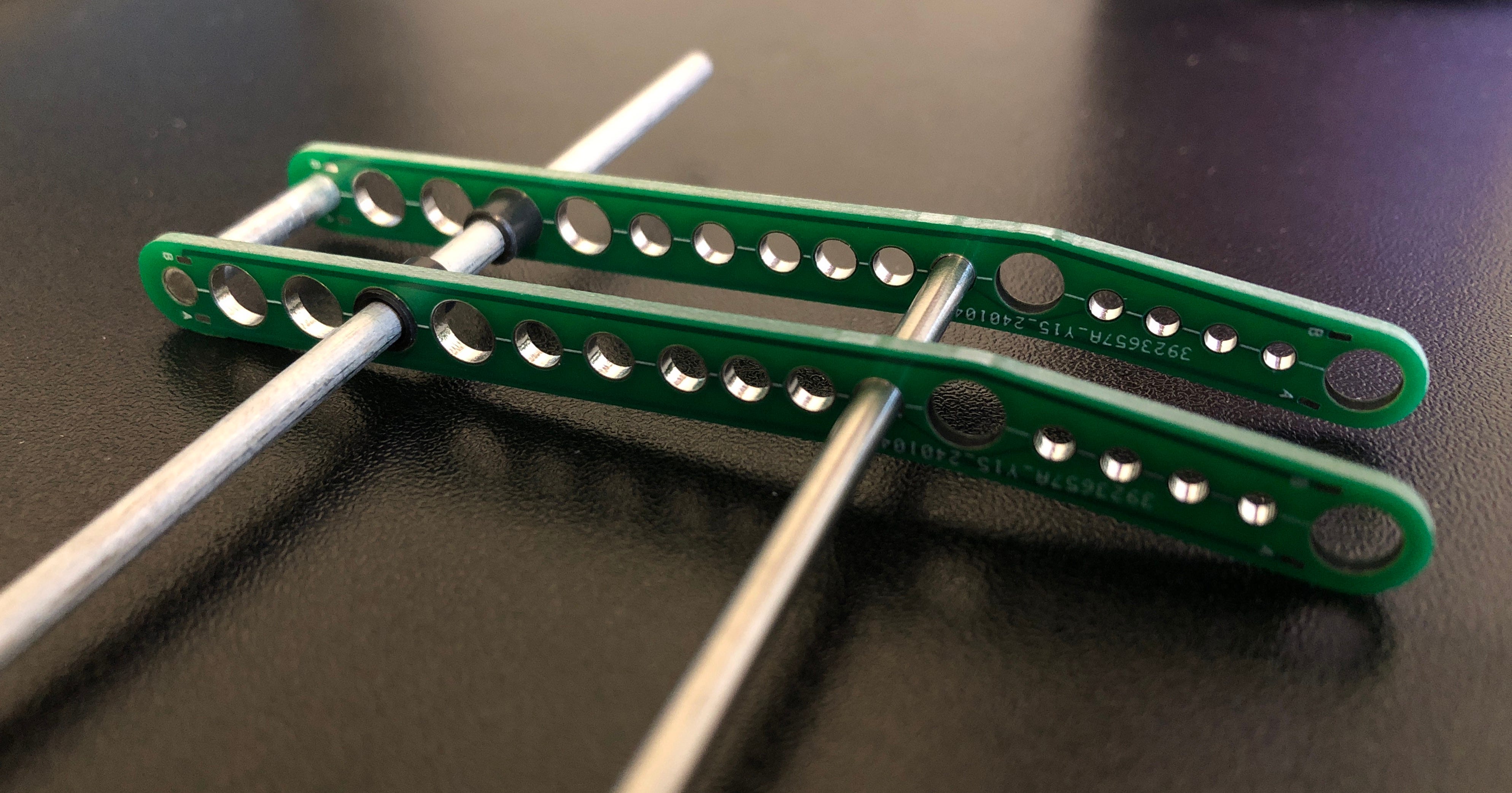
What if we use PCBs as structural components? FR4 fiberglass is stiffer than the 3D printed PLA we have been using and there is now a cheap way to cut them. Also, we can run wires cleanly along them to reduce clutter (almost like that’s the intended purpose!) This piece is to test if the hole sizes of the PCB manufacturer will work for our bearings and shafts. So far, it seems promising and holes are consistent enough between the boards of the same batch. We might use a PCBs as leg links or as a backbone for power distribution.
Front and back leg redesigns
The 2DOF latched leg was developed to make the squirrel jump higher, but it wasn’t mounted to the actual robot last semester because it was too bulky. The concept seemed to work, so we’re currently designing a smaller version. Based on the new spring test data, we can use shorter springs to achieve a similar energy storage, and theoretically, decreasing the leg stroke should not affect the performance too much.

The geometry is also redone to allow for a larger range of leg pitch. One of the main problems with our first squirrel robot, Pinto 1, is that the leg could not pitch backwards far enough for a diagonal jump. The other problem with Pinto 1 was the weak front legs. We are redesigning the front legs to use Dynamixel XL330 servos. The picture below shows the front leg assembly, with the left being the front of the robot.

While the previous design uses a 4 bar linkage for each leg, the new design has a 5 bar linkage, which allows the feet to move freely in the space instead of being constrained to a curve. In this design, each of the two leg has 2 servos, and an additional servo is put between the two legs to drive a cam to control the roll of the legs. Both legs are constrained by rubber bands, so that they naturally want to push inwards. When perching on the tree, the cam pushes out the legs first, then the cam rotates to remove support, so that the legs will grab the tree. When climbing, the grippers never lose contact with the tree, thanks to the gripper with fish hooks developed previously, which can easily be pushed forward but not backward. The picture below shows the cam that is used to push out the front legs.

To accomplish climbing motion, the leg needs to be able to move in a straight line. At the same time, we want the two servos to operate at the same speed so that we can get maximum power from both servos, and below shows the geometry of the linkage in climbing and walking motion. The red curve is the effective path of the gripper for climbing and walking.

With some adjustment of the relative location of the links in the above linkage and making the two servos rotate in opposite directions at the same speed, it can also make the gripper move in a relatively vertical straight path for jumping.

The connection between the front leg and the back leg needs to be redesigned, since both mechanisms are significantly different from the ones in Pinto 1. Before the back leg design is finished, we might develop a temporary structure to connect the new front leg with the old back leg, so that we can test the new front leg.
We hope to get back to regular updates this semester. See you in two weeks!
Structural PCBs is genius
Amazing leg shot