#4: Can't wait to prototype
More degrees of freedom, front leg redesign, test stands, and fixed-point arithmetic
Another two weeks and it’s time for more squirrel updates! It was a hectic time for both of us, with finishing up projects at our summer jobs, moving apartments, and troubleshooting car and laptop issues. However, we were able to make decent progress on both mechanical design and firmware, in preparation for prototyping by the end of this month.
Overall structure
Here is the updated squirrel assembly! There is only one rear leg mechanism, which helps reduce the width of the robot to make it look like a squirrel. We’ll add in the other leg once we verify the design and can start optimizing size. The chassis is a monocoque developed from the rectangular motor housing a few weeks ago, with a curve for aesthetics.
This version of the robot has the basic ability to jump and land, using two motors to power the rear legs and two spring dampers in the front to provide damping during landing. However, continuous jumping cannot be achieved in this version because the front leg does not have actuation to change the pitch between jumps.
Will there be yaw, pitch, and roll control later? Yaw is neglected at this point, because any yaw from disturbances will only make the squirrel turn, and the goal for this version is just to bound forward and check if our approach will work. Some drift in yaw would be okay. However, pitch and roll of the robot might get out of control rather easily, so we’ll need mechanisms to control those.
From the front, real squirrels running look like they are bouncing up and down, their front and rear alternating to contact the ground. In our case, strong pitch control will be similarly achieved with the combination of rear and front legs pushing on the ground.
However, even though the legs move very fast, they are designed to be lightweight and do not have much rotational travel, so there is little pitch control authority in the air. Like a real squirrel, we are thinking of creating a tail with two actuated degrees of freedom to control pitch as well as roll in the air.
It could be difficult to attach the tail motors, because the placement of the motors above the rear leg could reduce the mobility of the rear leg, or it would require an extra mechanism to relocate the motors.
The second approach is adding a motor with a small flywheel inside the body. This would add more weight to the robot due to the mass of the wheel required to get enough moment of inertia, but we can put this in a more convenient location, like the belly.
The third approach is adding a degree of the freedom between the rear leg and front legs, so that the front and rear half of the body could rotate relative to each other, which helps change the roll of the part about to touch the ground. However this could result in instability during landing because there is a good chance the front and rear half of the body will have different roll, and the feet won’t contact the ground at the same time.
So far we are leaning towards using a tail eventually, but let’s get the jumping done first.
Future front leg design
To achieve continuous jumping, the front leg needs to be redesigned to do more than damp the impact. We want to change the direction of the vertical velocity but preserve momentum in forward direction. To preserve forward momentum, the foot should be moved horizontally to follow the ground, but if that were the only degree of freedom, there would be no damping or springing effect in the vertical direction. We should make sure there are two degrees of freedom, and that the spring or damper does not apply any forward facing force on the ground.
A possible solution is using a lambda linkage and a motor to rotate it. The basis of the current front leg mechanism is actually a lambda mechanism.
The following picture shows the 4 bars in the lambda linkage, with the purple arrow showing the path of the foot during retraction. A motor would rotate the entire front leg assembly to adjust the direction of the purple arrow during the ground contact and ensure the spring never applies force in the wrong direction. The rotation of the entire assembly and spring rebound would push the foot down and back at the end of contact. By adjusting the torque of the motor, we can adjust the upwards “push” to change the pitch of the robot for launching.
The following picture shows another solution by replacing the orange rigid link above with a rubber band and removing the damper.
In this idea, when the foot contacts the ground the spring behind the upper link is stretched, which encourages the whole limb to rotate clockwise. This is intended to be mounted with the front of the squirrel to the right, so in the right configuration the ground reaction force would be transferred to a forward propelling force. A small motor at the upper right joint helps with this rotation to push the leg backwards. When the back leg jumps and the front foot is no longer in contact with the ground, there is little load on this linkage and the motor can easily move the foot forward again in preparation for the next jump.
Test stands
As we soon move into the first leg prototypes, we need to characterize different designs and pick out the best. Specifically, we need to collect speed-torque relationships of the brushless motors, the mechanical advantage profile of the twisted string actuator, and the force output of the rear leg assembly.
To measure the torque output of the motor, we can use something like the Tyto Robotics thrust test stand shown below:
This system measures torque output of similarly sized drone motors using two load cells that twist as the motor applies a torque on its mounting point, and additionally measures thrust force from the propeller attached to the motor using a vertical load cell that bends as the entire assembly pushes back. Our plan is to build something similar with load cells, using the same torque measurement concept but placing the third load cell at the output of the twisted string:
As the motor spins, it twists the string and bends the load cell on the right towards it. At the same time, the torque required to twist the string deform the two load cells mounted to the motor base. These load measurements can be collected with a few HX711 breakout modules, which read the small voltages produced by the strain gauges in the load cells and logged to a Raspberry Pi.
To test the jumping of the rear leg assembly, we can use a long rod on a pivot to approximate free motion in the vertical direction. The leg either mounts to the ground, foot pushing upwards, or to the end of the rod, foot pushing downwards. We can measure the force of the leg either with a load cell to measure bending in the rod, or one on the ground acting like a scale to measure ground reaction force.
The goal of this system is to not only characterize how much force the leg can put out, but also how that force is distributed over time. One feature of the leg linkage is the varying mechanical advantage, so we want to obtain plots of force vs. position to verify our calculations.
Motor control with DQ0 (Chris):
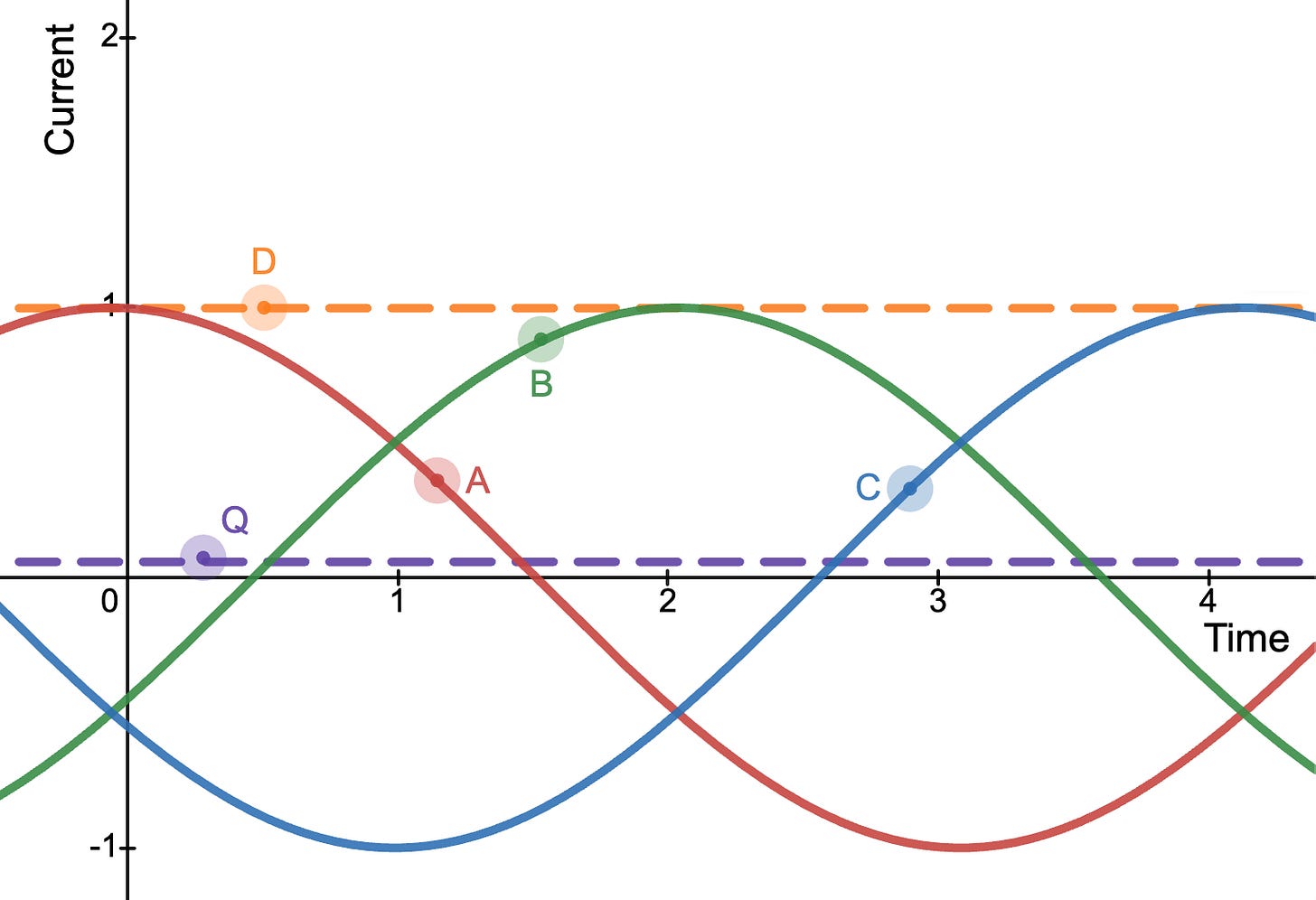
Last week I had some time to work on the FOC (field oriented control) motor algorithm. When our BLDC motor spins, there are three almost sinusoidal waveforms for the current in each of the phase wires, and the frequency of these waveforms depend on the speed of the motor. A defining feature of FOC is that the controller calculates the direct and quadrature currents of the motor, which transform the information in the three AC waveforms into DC values that are easier to interpret and control, allowing smoother and more efficient movement. The direct (D) component represents the part of the current producing magnetic flux that is parallel to the permanent magnets and does not produce torque, while quadrature (Q) is perpendicular and does produce torque. Generally, we want to minimize D and maximize Q for higher torque (except in the case of field-weakening, which we are not considering yet).

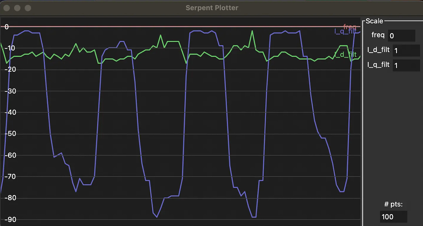
The important progress last week on the motor controller was implementing the DQ0 transform using only fixed point arithmetic. The Cortex-M0 processor on the motor controller does not have a floating point unit, is a bit slow compared to other commonly used microcontrollers used in FOC, and we are already close to both the flash and RAM limits. It’s becoming a challenge to make these mathematical operations fast and memory efficient yet retain enough accuracy to reap the benefits of the FOC algorithm. Some design parameters include the resolution and size of the sine lookup table, which power of 2 to scale the numbers with, how many bits to allocate to each variable, and during which points in the calculation to truncate the lower bits to avoid overflow.

Now that we have DQ current measurements, we can run a control loop to drive them to a desired value for the amount of torque requested. This involves a PI (proportional integral) controller and converting DQ voltages into ABC voltages using the inverse DQ transform. The inverse DQ transform is the same concept as before, but I ran into some interesting problems with 32-bit integers overflowing during intermediate calculations.
Next week, I’ll debug the inverse DQ0 transform and tune the current controller. Finally then, we should be able to use space vector modulation to drive the motor phases with a smooth sine wave.
Until next time…
This summer we’ve been doing a lot of ideation but not much testing. That will change in about two weeks when we’ll be back on campus and ready to get things made! Until then, we’ll be finishing up design work so that it can be applied soon.
This newsletter was a bit long and more technically detailed. Let us know if you like the detail, or you’d rather just see the overarching ideas. Anyway, thanks for reading!


Ideas and then details! Lots of details are always good and allows us to learn about what you guys are thinking and reflecting on! Great writing as always!